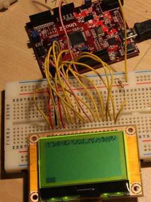
Graphical LCD Breakout Board
Last updated: April 28, 2012, 6:35 p.m.
I've got an on-going project to build a battery powered device. I want to be able to run the whole thing at 3.3V so I can easily and efficiently run it off a single LiPo cell. I also want to use a simple monochrome, graphical LCD for this project, but I couldn't find one that would run off 3.3V. For various other reasons, the project requires that the LCD is a classic 8bit parallel module as I had run out of hardware serial ports and bit-banged was making the refresh seem really slow. I found a few that would run the control lines off 3.3V but still needed some higher voltage to power the screen or back-light. Eventually I bit the bullet and decided to go with one of these from Farnell because it was the cheapest back-lit 128 by 64 pixel display I could get from them. It is a really good choice as it even includes electronic contrast control, something I was expecting to have to do in external circuitry. However, it isn't a nice 0.1" pitch module, it comes out to a 0.5mm pitch FPC connection.
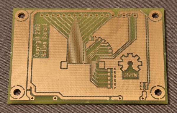
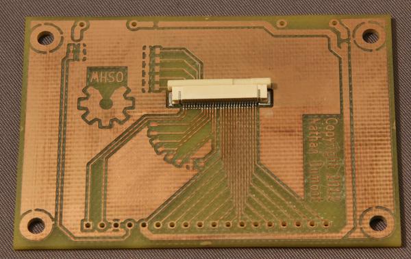
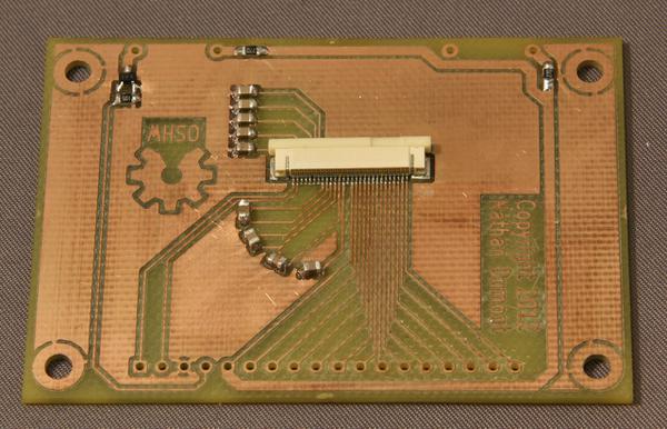
After a couple of failed attempts at trying to dead-bug the FPC connector with kynar wire I decided it really needed a breakout board. I laid out the board in KiCAD and I've included all the support parts, a set of capacitors for the multi-voltage LCD driver hardware and a MOSFET and some resistors to allow easy control of the back-light from a GPIO pin. The board is designed to be single sided, with the screen module stuck on the other side with a bit of double-sided tape. I added some mechanical mounting points around the edge. The back-light connections were un-routable without going to a dual layer board or significantly altering the geometry so I just added a wire on the finished board.
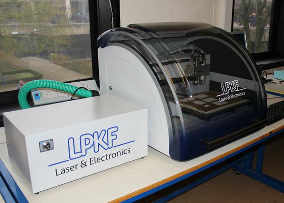
I actually got the board made at work using an LPKF precision PCB mill. This job was well within the capabilities of the machine despite the 0.2mm (~8mill) design rules used in the PCB layout. Only double sided copper was available so I used the layout for the other layer to ensure that the few through-hole pads were not shorted on the upper layer. Having the second layer has helped with the mechanical strength of the 0.1" header but the copper is only 18μm (0.5oz) thickness and I have had some hair-line fractures where the pads meet the tracks on the pin header.
Design Tips for Milling PCBs
These are a few things I learned from the process of making this board, they're not exhaustive, nor are they based on long experience, still they might be useful to someone.- Use as few hole sizes as possible.
- If you have to change the drill every time it takes longer to have pin headers drilled 1mm and through hole parts drilled 0.8mm, so modify all your pads to use 1mm holes before making Gerber files.
- Make mechanical pads as big as possible (much bigger than you would for through hole plated).
- Because there's no through-hole plating each pad has to stand up for itself. If you've only got a little pad on the board then it's not going to be as strong on single sided milled work. If you can leave more copper attached to the pad it'll be quicker to mill and be stronger.
- Kapton is a good alternative to solder mask
- If you mill your PCB you won't have any solder mask normally. It can help to use some heat proof Kapton tape (it's the translucent yellow polyimide tape popular in 3D printing circles.) This helps to stop the solder spreading too far, and can help when using solder wick to make sure it doesn't stick to the track.
Actually mounting the connector was done with a toaster oven and the previous version of this controller from Beta Layout. Some slightly past-its-best solder paste was pressed into service and a little clean up afterwards was required. The 0805 capacitors and resistors and the MOSFET were all soldered by hand with my old Weller TCP.
I've already posted the footprint for the open source hardware logo that I used on the board here.
Driving the screen
To drive the screen for test I hooked it up to my ChipKit Uno, this was to hand and is really easy to get going, it's also a 3.3V device unlike the Arduino Uno so made a good match for this project. I've hooked it all up to the first digital output header because this has the 8bit parallel port available on the extra row of pins. The back-light is just hooked into a PWM pin so I can use analogWrite() to set the brightness. The rest of the pins are just controlled with digitalWrite().
The LCD module datasheet is rather poor, however it does have the part number of the controller chip in the summary, after a quick search I found the datasheet for the actual controller IC and this has all the commands detailed in it. I've written a couple of wrapper functions for writing commands and writing data, the only difference between the two functions is the state of the data/command pin. All the pins are symbolically defined with #define macros to make the code more portable and I've added some defines for the data/command and read/write pin to make it easier to code. If you read the command register at any time you get a few status flags which are really handy for determining what state the screen is in.
The screen starts up with random 1s and 0s in the memory so I had to go through a blank screen loop first of all to make it all clear. The controller is designed for a bizarre 132x65 pixel screen size, depending on the mode you set the horizontal alignment of the 128 pixels is at one edge or the other which left me with four un-blanked pixels at one side of the screen which confused me for a bit.
Monochrome bit image converter
The Open Source Hardware logo on the screen was made by taking the logo from the website and passing it through a Python script I wrote which uses the Python Image Library (PIL) to scale the image, then compress the palette down to black and white. It converts each bit from 8 rows to a byte, writes this out in a C file then moves along one column. A C file with a byte array in it, saving this file to the sketch folder and using the image variable with row and column indices lets you access the image. I just copied the image to the screen with my code, this is a really easy and fairly efficient way to store data in the flash memory on the ChipKit.
Hardware pin outs
This is how I connected up the screen to the ChipKit, with the pin header at the top and the ribbon around the bottom of the breakout board Pin 1 is on the left as you look at the screen. Pins 26-33 on the ChipKit are Port E pins 0-7, for speed of access I used the PORTE/LATE registers in the sketch to read and write all 8 bits at a time.
| Screen Pin | ChipKit Pin | Function |
|---|---|---|
| 1 | +3.3V | Parallel/Serial (high = parallel) |
| 2 | +3.3V | 6800/8080 (high = 6800) |
| 3 | GND | GND |
| 4 | 3 | Backlight on |
| 5 | +3.3V | Power |
| 6 | 33 | D7 |
| 7 | 32 | D6 |
| 8 | 31 | D5 |
| 9 | 30 | D4 |
| 10 | 29 | D3 |
| 11 | 28 | D2 |
| 12 | 27 | D1 |
| 13 | 26 | D0 |
| 14 | 2 | Enable |
| 15 | 4 | Read/Write |
| 16 | 5 | Data/Command |
| 17 | 6 | Chip Select |
| 18 | 7 | Reset |
Comments
Posting comments is not currently possible. If you want to discuss this article you can reach me on twitter or via email.

