Laptop Battery to Phone Charger
Last updated: Aug. 28, 2012, 9:15 p.m.
I went camping at a festival this weekend, this meant 3 days in a tent with no power. Of course there are charging facilities at such an event, but they're not free and you can't charge your phone while you're asleep like at home. Previously I built a one charge boost charger to let you charge up a phone on the go, but that's only good for one charge of a modern phone and then it needs charging itself. I was camping with my wife for three nights and we both have modern Android phones which we used a lot so we needed 6 full charges over the course of the weekend. Looking around the lab here before we went I spotted the old ASUS EEE PC 701 extended battery and realised that would probably be quite a big capacity.
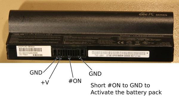
It turns out netbook batteries are perfect for this type of job, the ones I had were between 4400 and 6600mAh with a nominal voltage of 7.4V, this is a high enough voltage that you can just regulate down to 5V for a USB charged device. The circuit I used was the same one I made for the BigTrak project using the example layout from the LM2576 datasheet. This is a switch mode regulator with an efficiency between 75 and 80% in the voltage range used here, the advantages of using a switch mode regulator are that the heat sink requirements are much lower and when the battery is at full capacity it can be outputting around 9V so a linear regulator would typically have an efficiency around 50% or worse. The only trick with making use of these batteries is knowing how to connect them, through some rummaging in archives of a now re-structured EeePC user forum I managed to find that someone had figured out the pin out of the connector enough to make the battery work for me. There seems to be a switch line that has to be shorted to ground to make the battery produce volts on the main terminals. I've labelled up a photo. I shorted the switch line to the ground contact on the right hand end and then used the ground and power pins on the left to get the supply for my regulator. The contacts should be 5mm wide spade connectors but I couldn't find anything exactly right at short notice, the contacts are too narrow for a standard 1/4" spade connector so I used some miniature spade connectors from Maplin, they're a little loose at only 3.8mm wide but it worked okay in static use.
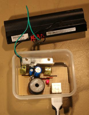
Other than the regulator support components the only things I added were an LED and a twin stacked USB port salvaged from an old motherboard. To charge the laptop battery you need to plug it back into the laptop and leave the mains lead plugged in. The advantage with my regulator over just using the USB ports on the laptop is that these netbooks only power the USB ports when running so you would have had to use a big chunk of the battery to run the processor. From a hurried internet search as I was packing I found that most Android phones consider a supply to be capable of supplying high current like a wall charger if the two data lines of the USB lead are connected together. iPhones have a special pull up or down voltage on the data lines but I have no idea of the specifics. The regulator is capable of supplying up to 3A continuously so two phones can charge at high current (~1A) at the same time with no problems.
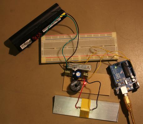
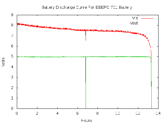
Lithium batteries can be damaged by being over-discharged so I wanted to check that these battery packs had the protection built in, which is common in laptop batteries. I rigged up the regulator with a 12Ω power resistor on a heatsink across the output, this draws about 400mA at 5V. To monitor the voltage of the battery while I was discharging it I wrote a tiny Arduino sketch that measured the input and output voltages on the regulator board and wrote those out to the host PC over serial. The output voltage was regulated to 5V so would only drop below if the regulator got into its drop out range so I connected this directly to the analogue input A1. The input voltage from the battery could be up to 9 or 10 volts but not more than 10 so I just used a potential divider with two 1k resistors so that the measured voltage is half the real voltage, this is compensated for in the Arduino code. I used 1k as I'm not sure what the input impedance of the analogue to digital converter on the ATMEGA328 is so I wanted to make sure the resistors weren't too big. The PC just wrote all the text from the Arduino to a text file producing two columns of numbers which can be plotted in GNUPlot. As you can see the battery pack dropped to about 5.4V (2.7V per cell) then the protection cut-out kicked in and it dropped to zero volts. This is a little lower than I would have picked but probably safe enough. If the batteries had no protection (like you see in some model plane lithium battery packs for example) the battery voltage would have dropped quickly to near zero but not an immediate drop from 5.4 to 0V in 30 seconds. Ideally you shouldn't discharge the battery below about 80% capacity, and probably not below about 7.2V open-circuit in total to get the absolute best life out of it, but for an obsolete laptop battery I'm happy it won't die after one use like this. A rough calculation from this graph shows that the battery is still near its design capacity,
Expected capacity = 5.2Ah * 7.4V = 38.5Wh Consumed power = (5V * 5V) / 12Ω = 2.08W Measured capacity = 2.08W * 13h = 27.04Wh Calculated regulator efficiency = 27.04Wh / 38.5Wh * 100 = 70.2%
So the regulator efficiency is within the expected bounds. Of course the current drawn will affect the efficiency because for optimum power transfer you must take into account the internal resistance of the source and match that. However the experiment satisfied me that I wasn't going to irreparably damage all the batteries by leaving them to charge phones all night.
I'm happy to report that the charger worked a treat in the field!
Comments
Posting comments is not currently possible. If you want to discuss this article you can reach me on twitter or via email.


