Z80 Project Mark 2: More Dodgy Mods
Last updated: Oct. 6, 2009, 3:18 p.m.
So, I got some lights flashing over two weeks ago and then went quiet, "what's been going on?" you may well ask. Once I got the lights flashing, I wrote another demo that does a chase across the row of LEDs, this would show up if any of the tracks on the data bus were shorted as each led is lit individually and is driven by a single bus line. Once I'd done that I started work on the serial port code for the PIC's onboard serial port. The basic send and interrupt on receive code is working so it echoes each character it receives back at the moment. However to test the code in the PIC I needed a nice serial-terminal application so decided to write one with PyGTK, threading and python-serial. I've got that working fairly well now, once I've developed it a bit more I will probably release it somewhere.
However, I hit something of a problem while studying data sheets. It explains why no one has tried this whole running DMA while the Z80 is in reset idea before. Basically while the Z80 is held in reset the MREQ, IORQ, WR and RD lines are set to their inactive state (that is logic 1) not high-impedance as I had assumed. This is perfectly reasonable for a CPU and something I'd not really thought about having only really used microcontrollers in the past.
This would mean that I could not write to memory while the Z80 is in reset because I don't have access to the control bus, and also means that the 10K pulldown resistor I had put on the BUSACK line would not work as planned. To get it to work the way I had set it up I would have to run the Z80 for long enough to start a proper DMA cycle, load the memory and then reset the Z80. The timings for DMA immediately after startup are not well defined and I'm not sure how many instructions the Z80 would process before relinquishing the bus, I suspect at least one. This is potentially problematic as the memory I'm using is FRAM and could still have instructions from the last boot in it when the system starts meaning the CPU could potentially start writing garbage to IO peripherals or other problems before it is stopped and reset.
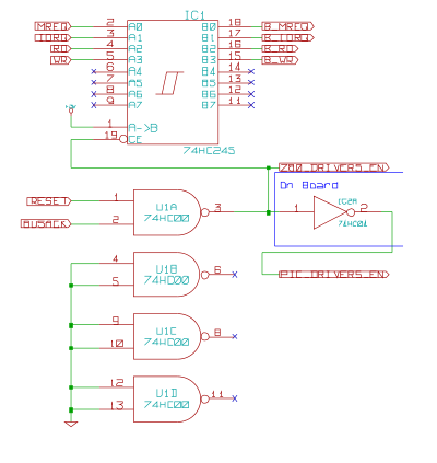
To overcome this I added more hardware. This is similar in function to a previous design I had developed and more or less forgotten. The control lines are now buffered like the data and address, through a 74HC245 hardwired to one direction (since I didn't have any 541s around). The enable for this and all the other Z80 bus driver chips is derived from a single NAND gate fed by RESET and BUSACK. If either of these lines is active (low, 0) then the output of the NAND gate is high, and disables the Z80's control of the three buses. The NOT gate that had previously been driving them is now used to invert this signal to drive the high address latch from the PIC. Since the RESET line to the Z80 is an input it can safely be pulled low (as is shown in the main diagram. This ensures that when the system starts up the Z80 is in reset and none of its bus drivers are active.
Now I plan to write some basic debug functions for the PIC that allow memory read and write from the host PC, then check out the address bus and ensure that there are no shorts or missing connections.
Comments
If you want to discuss this article you can reach me via email.