VGA Primer
Last updated: July 13, 2011, 9:51 p.m.

Video Graphics Array "VGA" is a standard for computer display. It has a lot going for it in the hobby electronics field as it is a pretty simple standard and quite straight forward to implement with sufficient signalling speed, there are also a lot of monitors around to test projects on! Colour is a lot easier to generate on a VGA monitor than on a composite video monitor, but it requires a lot more speed as the frames are more detailed and there are more signals to generate.
Defining the screen

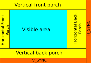
VGA Regions:
Example timings for a 640x480 display
| Region | Time |
|---|---|
| H_SYNC pulse | 2.7μs |
| Horizontal front porch | 0.6μs |
| Horizontal display | 25μs |
| Horizontal back porch | 1.9μs |
| V_SYNC pulse | 55μs |
| Vertical front porch | 277μs |
| Vertical display | 13.3ms |
| Vertical back porch | 914μs |
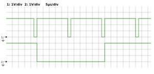
Signal diagram of a V_SYNC pulse (Ch2) and H_SYNC pulses (Ch1)

VGA Sync Traces: Horizontal and vertical sync traces for VGA.
A VGA display is built up of a number of lines, each line is made up of the same number of pixels. Defining which line of the screen the display is on depends on two "sync" signals, pixels are pushed out at a constant speed between these signals with no actual pixel clock. The H_SYNC signal is a TTL compatible logic signal which is high throughout each line and low for a short period (less than a couple of microseconds typically) at the end of each line. Within the "active period of each line there are 3 regions, the "front porch", this comes after the last sync but before the first valid pixel, the main display where the pixels are drawn and the "back porch" after the pixels are done. By varying the relative sizes of the front and back porch regions the relative position of the active display can be shifted left and right. This allows the display to be centred on your monitor, there are typical values for these regions shown in the timing diagram.
Similarly a V_SYNC signal is used to define when the whole screen has been drawn and the display should start again at line 1. This is a much longer signal typically taking at least a couple of lines. This is a legacy of CRT monitors where the beam had to scan back up to the top of the screen. The vertical display works in a similar way with a sync period followed by a front-porch, visible screen and then a back-porch region. So a vertical frame effectively has more lines than there are pixels in a column on the screen e.g. a 480 line high display is made up of a total of 525 lines.
The actual sync signals are TTL compatible, this means that they are compatible with 3.3V CMOS as a 1 is signified by 2 volts or more. They are both negative pulses, i.e. they are low for the sync period and high normally.
Colour display
VGA relies on 3 analogue signals to define the colour of the current pixel, one each for red, green and blue. They are typically defined as between 0 and 0.7 volts although 0-1 volt often works fine. In truly analogue displays the value can vary by any arbitrarily small amount, giving no definite limit to the number of colours. Typically however the number of colours is defined by the number of bits assigned to each colour channel. The input impedance of these analogue lines is 75Ω (like composite video) this can be used in simple DAC circuits to turn ordinary logic level outputs into analogue values in the right voltage range.
The VGA display uses the horizontal sync period at the end of each line to calibrate the colour. During this period all of the colour lines need to be at their minimum value, if they're higher than the minimum then that colour will have a reduced dynamic range during the following line. Note that it isn't possible to have a negative intensity of a pixel in the screen so if the voltage on a colour line drops after the sync signal that colour will remain at its minimum intensity.
Connector

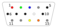
Connector Pinout:
| Pin | Function |
|---|---|
| 1 | Red |
| 2 | Green |
| 3 | Blue |
| 4 | IDN2 |
| 5 | Ground |
| 6 | Red Ground |
| 7 | Green Ground |
| 8 | Blue Ground |
| 9 | Connector signal |
| 10 | Sync Ground |
| 11 | IDN0 |
| 12 | IDN1 |
| 13 | H_SYNC |
| 14 | V_SYNC |
| 15 | IDN3 |
The image displays a minimal wiring for the VGA 15-pin high density D-type connector. This is drawn from the solder-side on the generating device. Note that each of the three colour signals have their own ground return signal, and there is a joint ground signal for the two sync lines. In most systems it is sufficient to just join all these to the system ground along with the general ground pin. If you have a proper DAC solution however you may have a separate analogue ground which may improve signal quality especially for higher resolutions. Pin 9 is typically connected to a 5V signal on the host to identify when the VGA connection is in use, this is used by a lot of monitors to switch to the appropriate input and without it you may find the monitor does not turn on.
There are also a set of return pins which can identify the monitor's capabilities (marked IDNx on the diagram). In the most basic implementations these pins are simply shorted to ground or not to indicate whether the monitor can display colour or higher resolutions. These simple qualifications are out of date now and not really useful, the pins can act as a form of synchronous serial bus similar to i2c which can provide more detailed monitor information about make, model and capabilities. I've not experimented with these capabilities and have no idea what the practical implications of using these pins are. For a simple VGA display you can safely ignore them, just leave them disconnected.
Comments
Posting comments is not currently possible. If you want to discuss this article you can reach me on twitter or via email.