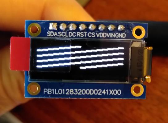
Midas Graphic OLED
Last updated: Nov. 11, 2020, 11:31 a.m.
I recently included a Midas Graphic OLED 128x32 pixel display in a product I'm developing at work. The OLED is available from Farnell for a very reasonable £7.61. It's got a 0.1" pitch header for comms and 4 M2 mounting holes which makes it ideal for DIY/prototype products that don't have custom enclosures to mount a bare LCD glass panel nicely.
The big problem is the documentation which is worse than non-existent. It's confusing, misleading and in places just plain wrong. The datasheet seems to have been assembled by someone copying and pasting bits from the controller datasheet with no understanding of what the product does.
I eventually figured it out and got it working, so here are my notes.
Controller
It seems the controller used in the module is an SSD1306 which is a generic 128x64 LCD driver. Since this module is only 128x32 obviously half the memory isn't connected. Adafruit have the datasheet for the controller here. This helps greatly in figuring out the functionality but some things are still guesswork as the schematic is unknown and there are a lot of pins on an LCD controller.
Pinout
The pinout in the datasheet is very confusing. The controller chip supports a wide range of data connections from 8bit parallel to I2C. However which mode is enabled is selected by tying pins on the control chip to certain levels and these are done somewhere inside the module. It is wired in 4 wire SPI mode despite the datasheet discussing I2C and 3 wire mode. So the pinout should be:
| Pin | Label | Purpose |
|---|---|---|
| 1 | SDA | SPI COPI |
| 2 | SCL | SPI CLK |
| 3 | DC | Data/#Command connect to GPIO, low for command high for data |
| 4 | RST | Active low reset input |
| 5 | CS | SPI Chip Select |
| 6 | VDD | 3.3V |
| 7 | VIN | 5V |
| 8 | GND | 0V |
I've not quite figured out all the power supply options, I think it can derive power supply options from just one pin but the exact options were not immediately obvious, I had both 3.3 and 5V available and the above connections do work.
Sending commands
The module uses a fairly typical pattern for these small graphical displays, it has a set of commands and a separate channel for data. By setting the DC pin low bytes sent via the SPI interface are interpreted as commands, setting DC high will treat the bytes as data. You cannot use the 3 wire SPI mode which uses 9 bit words with the data/command as an extra MSB, this is mentioned in the datasheet and is supported by the controller but the pins needed to enable this mode are hard-wired to 4 wire mode inside the module.
Initialisation
The initialisation code in the datasheet doesn't work either. I've adapted it here to get the display up and running. This assumes that oled_write_cmd() writes a single byte via SPI with the DC line set low and oled_write_data() writes a single bytes via SPI with the DC line set high. Before running this snippet I set up the SPI periphreral (CPOL=low, CPHA=1st edge, MSB first, 8bit) and the GPIO peripherals. Then I pulse the RST line low for about 1ms to make sure everything is reset.
oled_write_cmd(0xae);   // display off

oled_write_cmd(0xd5);   // set display clock
oled_write_cmd(0x71);   // 105Hz

oled_write_cmd(0xa8);   // Select multiplex ratio
oled_write_cmd(0x3f);   // default is 1/64, 0x1f is 1/32

oled_write_cmd(0xd3);   // setting display offset
oled_write_cmd(0x00);   // 00

oled_write_cmd(0x40);   // Set display start line
oled_write_cmd(0x8d);   // enable charge pump
oled_write_cmd(0x14);

oled_write_cmd(0xa1);   // set segment remap

oled_write_cmd(0xc8);   // set COM scan direction

oled_write_cmd(0xda);   // set COM pin configuration
oled_write_cmd(0x20);

oled_write_cmd(0x81);   // Set contrast
oled_write_cmd(0xff);

oled_write_cmd(0xd9);   // Set pre-charge
oled_write_cmd(0x22);

oled_write_cmd(0xdb);   // set deselect vcomh level
oled_write_cmd(0x40);

oled_write_cmd(0x20);   // set display to "horizontal" mode so all 4 rows can be written in sequence

oled_write_cmd(0xa4);   // set display to show RAM (0xa5 drives every pixel regardless of RAM

oled_write_cmd(0xa6);   // set not inverse (0xa7 inverts pixel colour)

oled_write_cmd(0xaf);   // display on

vTaskDelay(100);

for(int k=0;k<4;k++)
{
    for(int i=0;i<16;i++)
    {
        for(int j=0;j<8;j++)
        {
            oled_write_data((0x8080 >> i) & 0xff);
        }
    }
}
Once that's run you should see the OLED light up and a pattern of diagonal lines across the whole display. If the screen doesn't light up, something is wrong with wiring or the initialisation code. If the screen lights up but there are random dots illuminated then something isn't right in the memory layout or COM direction/mode.
In this mode you should be able to write 8 rows (k=0;k<8;k++) before it loops back around but the second 4 rows won't be visible because the screen only has 128x32 pixels even though there's memory for 128x64. After 8 rows it should start writing at the top of the screen again. There are commands to go back to address zero with a single command after writing the 4 visible rows instead of writing all this invisible memory. Alternatively you can use the extra memory for paging information in theory, check the controller datasheet for changing where row 0 of pixels are read from.
Comments
Posting comments is not currently possible. If you want to discuss this article you can reach me on twitter or via email.
