How not to build a RepRap
Last updated: Dec. 24, 2011, 4:03 p.m.
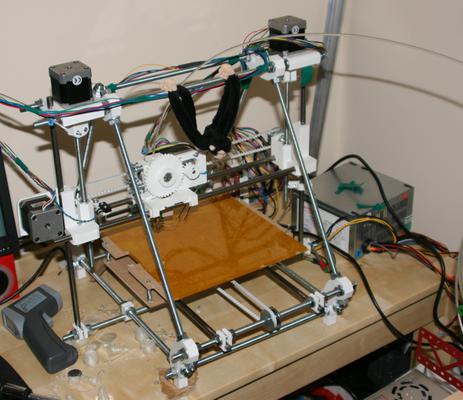
Actually I have a working RepRap now so it isn't all bad, but there are plenty (too many?) guides about what to do to make a RepRap, I thought I'd just point out the problems and mistakes I made building mine.
Video Summary
What is a RepRap? In case you've come across this article without knowing what a RepRap is, I recommend looking at the wikipedia article then if you want to know more reprap.org but be warned the official week gets specific and technical very quickly. But for a quick summary RepRap stands for Replicating Rapid-prototyper and refers to the purpose of the machine (rapidly prototyping 3D plastic parts) and the fact that most of the complex 3D components of the machine can be printed by itself so it can 'replicate'. There are great debates about whether a machine made out of steel rods and bolts and assembled by hand has really replicated itself when another is made but frankly I don't care, all I wanted was a cheap rapid prototyper.
Assembly
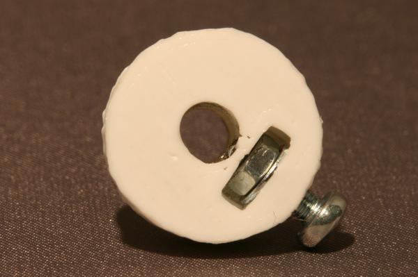
I bought the parts from a bunch of different suppliers. With the RepRap you start at around £600 for a complete kit and go down to around £300 for a one off build where you get the cheapest supplier for everything or scrounge parts. I think mine has cost a little less than £400 with minimal scrounging and buying some parts ready to assemble for cheapness. I had no problem getting specific parts (belts, extruder and controller PCB) from eMakershop a kind of single purpose eBay. The printed parts were from RepRapLTD, the company run by Adrian Bowyer and are (as you'd expect) pretty good quality. I've got two complaints about them, one is that they're PLA which melts cooler than ABS which makes it better to work with, but has meant that my motor mounts get soft if I run the steppers at anything like full current. The other is that the toothed belt pulleys were a bit sloppy so the captive nut spins when you try to tighten the grub screw, I've also found they actually deform after some time, giving them an oval hole. I've printed some of my own, putting the fill density up to try and make them a bit tougher but I think I'll be buying some aluminium pulleys and threading them properly soon.
The steppers I used were from a UK supplier Zapp Automation. I got 4 of the 1206A for the 3 axes (2 for Z and 1 each for X and Y) and one of the 1684A for the extruder. I think I'd go for 5 of the 1684A if I did it again. It has slightly higher maximum torque than the 1206A which is potentially handy for the extruder, but more importantly for the other axes it has a pre-ground flat on the shaft and much longer wires. The 1206A comes with 6 wires so it can be connected up in uni-polar or bi-polar mode but don't worry connecting up the ends of the coils and just leaving the center taps disconnected works fine.
Probably the trickiest part of building the thing is getting the order of assembly right. I think I built the extruder about 3 times before I got it all together and attached to the X carriage. There are so many instructions and they all reference one another, following all of them is a feat of memory and attention to detail. I was following Adrian's Prusa Notes because the parts he sells are slightly non-standard, the 'official' Prusa assembly notes (and visual guide) as well as the instructions for Wade's Extruder and notes on building the electronics. All these pages refer to each other at some point and try to tell you when to change things but unless you are a lot more patient and thorough than I am you're likely to get lost between the instructions and end up doing things in the wrong order.
Probably the most annoying one of these missed instructions was the note to say that the chip specified in the electronics bill of materials is the WRONG PART. I ordered the parts based on the BOM, paying attention to what parts I needed for my version and option set, but I didn't notice that I needed an ATMEGA644P rather the plain ATMEGA644 part. The trouble is the parts list is maintained on someone's private GitHub account and although helpful community members have made notes on the main Wiki page about it, there's no way for them to fix the actual BOM.
Electronics
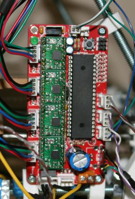
I built the Sanguinololu controller board. Apart from the problem with the wrong microcontroller part number in the BOM I also had some difficulties with programming the firmware. I built the board up with the TTL-RS232 header option for PC interface as I have a couple of these leads and I wanted to leave my options for hooking up an ARM microcontroller or something less than a USB host capable PC as a controller. I programmed the bootloader easily with the ISP/SPI header on the board using an Arduino as the programmer, that was the most straight forward part of the build I think. When I came to use the USB to serial adapter header though it wouldn't work. I had both the FTDI break-out lead and the SparkFun programmer board and neither would work. After investigating the circuit diagram I found two more BOM errors and a bad track. The power pin of the programmer (designed to allow USB powered projects) was connected to the 5V rail on the PCB which was being supplied by the on-board regulator. This is out of spec for USB as you shouldn't try to push current back up the power line to a host and the host supply could be down to 4.75V and still in spec. I cut this power track with a scalpel and moved on. The next problem was a joint revision issue and part segmentation issue. There's an added header on the latest board next to the microcontroller that allows the USB programmer interface to be disconnected from the reset line, this makes sure you don't send inadvertent reset commands when connecting the USB port or starting other software. I fitted this but I still couldn't get the reset line to work when I sent a program to it from the Arduino software on the PC. I eventually found there was a 0.1uF capacitor in series to make sure reset signals were pulses regardless of how long the serial line changes for. This is a fairly standard "trick" with FTDI serial interfaces using a handshake line for reset, but the capacitor was in the support components for the USB port in the BOM, not in the serial header support components, so I hadn't fitted it. Adding this suddenly it all came to life.
Running Getting the software going took the longest I think. There are two main ways to go with the software at the moment, one is the RepRap Host software, written in Java which is meant to be a one-stop solution. Unfortunately it lacks ability in converting STL files (the standard 3D model format used on Thingiverse and as export from most CAD software) to G-Code (the standard CNC command language used by most open source miller/printer type projects). It often seems to draw a mess of lines from a simple STL file generated from a valid 3D model. The second option is a collection of python scripts known collectively as PrintRun. This provides all the interface needed to convert and print files, but relies on calling a back-end program called Skeinforge. Skeinforge is a somewhat arcane piece of software able to do almost anything (even supporting CNC milling as well as 3D printing) unfortunately this makes it extremely complicated to set up. I ended up using a branch developed specifically for RepRaps called SFact which is relatively well documented and is pre-configured to more or less 'just work'. The big difference between these two pieces of software, and something that caught me out when first trying both is the extruder settings. The extruder on the RepRap (and others like the Makerbot) has been based on a stepper motor for some time. This means it can very accurately control the amount of plastic that is fed into the extruder and therefore the amount that is laid down. For the RepRap Host software and old versions of Skeinforge the measurement of "Steps per mm of extrusion" in the firmware was the steps per mm of plastic extruded from the nozzle, for modern versions of Skeinforge (ans SFact) the setting in the firmware should be steps per mm of filament. Since my RepRap is running a standard Wade's Extruder with 3mm filament and 0.5mm nozzle the difference between these two numbers is a factor of around 36, so when I had the steps per mm of filament set and was running RepRap host it was sucking in 36 times too much filament which just meant the nozzle pressure got very high and the stepper couldn't push more plastic in. I then managed to make the same mistake again when I tried moving to the SFact generated G-Code, the extruder was pushing in enough plastic to generate 1mm of extruded plastic when it thought it should have generated 36mm of extruded plastic, so nothing visible was happening on the bed. I'd advise go straight to SFact and configure your firmware with steps per mm of filament to start with and ignore the RepRap Host software for the time being.
Comments
Posting comments is not currently possible. If you want to discuss this article you can reach me on twitter or via email.
