Stripboard Circuit Construction
Last updated: May 21, 2014, 9:59 p.m.
Before cheap prototype PCB services like OSHPark, Ragworm and iTeadStudio options for building circuits for prototype or hobby projects were much more limited. You could etch your own board, carve a board out of copper clad with an abrasive tool, wire-wrap it all or use stripboard.
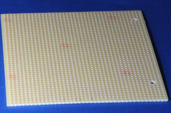
Stripboard, sometimes known as Vero-board (after a popular manufacturer) is a kind of circuit board, usually a cheap substrate like SRBP, with long strips of copper about 2mm wide running the length of the board. Holes are typically punched on a 0.1" (2.54mm) grid across the board, making it easy to fit traditional through-hole components.
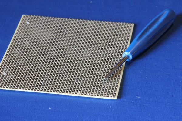
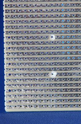
The basic technique of construction is to use a small drill type tool, known as a spot-face cutter, to cut the long traces to make separate parts of the circuit. Wires are run, perpendicular to the copper tracks to create links in the opposite direction, allowing complex circuits to be built up.
Design For Stripboard
I use an old-fashioned approach to strip-board layout using a pencil and squared paper. There are layout tools out there, and it is possible to do the design using more traditional CAD tools like KiCad if you are very strict about grid sizes and only routing in one direction on each layer. I still use KiCAD to draw out my schematic, it is quick and easy to do, and having a schematic with neatly labelled pin numbers is a real help when doing a layout. Once the schematic is drawn it's often helpful to get hold of all the parts for your project, especially if you have connectors or other large parts that don't have "standard" footprints.
Like all circuit board design the best place to start is your mechanical constraints, board size, where components need to be for heat-sinking or for access to connectors. Make sure you constrain your design area to the amount of space you have if you're limited on space. Always leave plenty of room around mounting holes, for an M3 fixing I usually leave a 1 hole gap all the way around and cut the three tracks that run through the hole.
Because the tracks only run in one direction on traditional strip-board, it is important to try and get an un-interrupted run for traces like power. You need to take care to keep a track for your 0V rail clear as well, and try and link everything back to this one track rather than daisy-chaining ground. Even in low power circuits on stripboard it is easy to get into bad grounding problems if you just jump from point to point. Obviously jumping a long wire to the ground trace takes up more space than a short hop to a nearby component but it is usually worth it.
The usual trick with ICs is to put them perpendicular to the tracks and run a line of track-cuts underneath the middle of the chip. Remember you can leave out a track cut if you do need to join two legs of the chip together. With resistors there are basically two ways to mount them, either flat on the board or vertical with one leg arching over and back down into the board. As a rule of thumb, if you need to join two adjacent traces, or two traces with just one trace between them, a vertical mounted resistor will be the way to go. If you have 2 or more traces under the resistor you can normally bend the legs to allow it to fit flat to the board (assuming a typical 1/4W resistor).
Making wire links perpendicular to the direction of the tracks is common practice. You can get packs of jumper wires for use with breadboard that I've often seen used on stripboard, I recommend you don't do this. For one thing they're really expensive if you only use them once, and once soldered you'll never get them clean enough to use in breadboard again. I also recommend colour coding wires in your design, especially ground and power and a lot of jumper link packs are colour coded by length so that wouldn't work. The best way to make good links in stripboard is to use a solid core wire (I use 1/0.6 wire, "bell wire" from Maplin because you can buy it in 10m lengths of different colours rather than 100m of one colour). Strip one end of the wire, use a pair of pliers to get a good tight bend, measure out where you need to start stripping the insulation off the other end and cut just past that. Strip off the insulation, bend the new end with pliers and you should have a nice straight link without excessive loops of wire above the board.
Cutting Stripboard
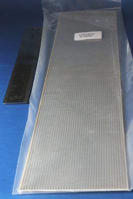
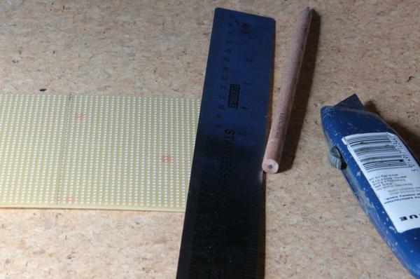
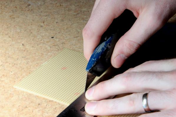
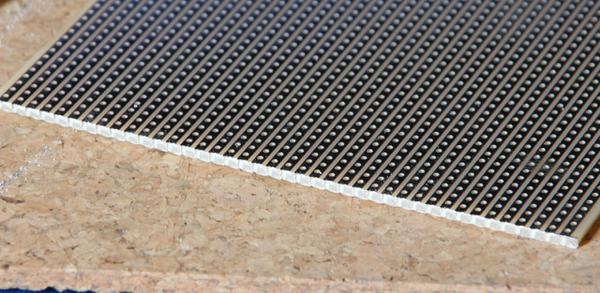
I normally buy stripboard in large sheets (like this one from Farnell). You can always cut off a much smaller piece to make a smaller circuit, but the larger the sheet you buy the cheaper it is per unit area. To cut up stripboard, the best way is with a good Stanley-knife and a steel ruler. Place the board on a cutting mat and place the ruler where you want to cut the board. It's best to use a row of holes as perforations rather than trying to cut between rows. Run the knife across the copper side of the board against the ruler several times until there is a deep cut in the substrate, and the copper is all cut cleanly. Finally place the cut above the edge of a desk or table, preferably a good square edge, not a rounded one, and press gently to snap the board along the line. I often use a normal metal file to just clean off any sharp edges and check that there are no stray bits of copper along the cut.
Tools
The essential tool for stripboard work is a tool for cutting tracks, they're known as a spot-face cutter or track cutter. There are a couple of styles out there, one that looks a bit like a drill with a long cutting blade, and another that looks like a sharpened screwdriver with a flat cutting blade. I strongly recommend the drill type, they work better and leave fewer copper strands, for value you probably won't beat this one from Farnell, but if you're in more of a hurry, this one from Maplin is actually the one I have. To cut a track, use the spot face cutter tool, hold it in one hand and press it firmly against the stripboard. Twist it round making sure to cut deep enough to cut all the way through the width of the copper and make sure you don't leave any bits of copper hanging on to the end of the copper tracks.
The holes in stripboard are usually about 1mm in diameter, this is fine for most components, but can get a bit tight on higher current parts or some connectors. Opening out the holes is pretty straight-forward as they are not through-hole plated typically. You can make the holes bigger with a sharp craft-knife or scalpal if you are very careful, but the best way is with a tapered reamer. The Hall one I've got comes from Farnell is a little pricey but should last a lifetime and makes the job of cleanly opening out holes a breeze.
You'll probably want a steel ruler and a good knife if you intend on cutting the board. You may want a drill either a cordless or even just a hand drill if you want to drill mounting holes. I sometimes use a file for cleaning a cut edge, but be careful you don't rip up the copper and drag the ends of the tracks over one another. You'll need the usual side-cutters, pliers and a soldering iron.
Troubleshooting
If you find a problem with your circuit built on stripboard, it is usually one of a few things:
- An "out by 1" error where you've run a wire to a row that is one away from where you meant to get it. This can be hard to spot because it can be difficult to keep your bearings when swapping from component to copper side of the board.
- A missed track cut. This is a faily obvious one but it comes up a lot, especially as the circuit becomes more complex. I advise going carefully along each row and looking at what is connected together and making sure you didn't forget a cut. It can be missed when doing the layout or when you are copying the layout to the board.
- Copper whiskers. It can be easy to accidentally leave a strand of copper at the side of a track cut which is still connecting what appears to be a cut trace. You can also get a bit of detached copper that is no longer attached to the board but has a tiny join to one of the tracks that has been cut, if this swings sideways it can easily short to a neighbouring track. Similarly when you cut off a piece of stripboard, you can leave rough edges, make sure there is no copper track flapping around on the edge.
Comments
Posting comments is not currently possible. If you want to discuss this article you can reach me on twitter or via email.
