RepRap Part Replacement
Last updated: April 10, 2012, 9:15 p.m.
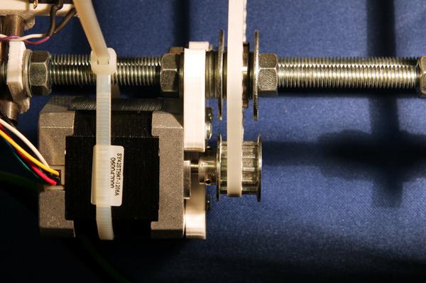
Since my How Not to Build a RepRap article last year, among the many other projects I've been tinkering with are several upgrades to the RepRap. I've changed the pulleys, to reduce backlash in the X/Y plane, the Z axis couplings and lead screws have been replaced to improve vertical reliability and I've built a new power supply.
Check out the video for some footage of me pointing to bits and talking about them.
New Pulleys
The new pulleys I've used were from Farnell (note that the photo on that page is entirely wrong at time of writing). They're 12 tooth which isn't a nice number for steps/mm calculation (see below) but they are the smallest size that I was happy I could get enough threads in. Smaller pulleys had only an 8mm bush on them which means with a 5mm bore you only get 1.5mm of thread which is likely to be a bit weak for the kind of force these pulleys face. Since I made this choice I have seen another Mendel at the Cardiff Hackspace which was using the smaller diameter pulleys with a grub screw put in between the teeth rather than the bush. This approach will cause additional wear on the belt and may cause a reduction in tension at some parts of the cycle which is why I decided to go for the larger pulleys. I can't say I've noticed any difference in dimensional accuracy using the Sprinter firmware, one of the first things I did was print a simple design I'd done and compare them to see if there was any noticeable size difference and it seems any rounding errors are below the overall accuracy of the system so they disappear into the noise.
steps per rotation = stepper motor step count x microstepping = 200 x 16 = 3200 belt moved by one rotation (mm) = teeth x belt pitch (mm) = 12 x 5 = 60 steps per mm = steps per rotation / belt moved by one rotation = 3200 / 60 = 53.333
Z Axis lead screws
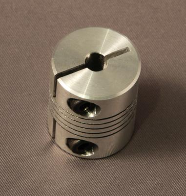
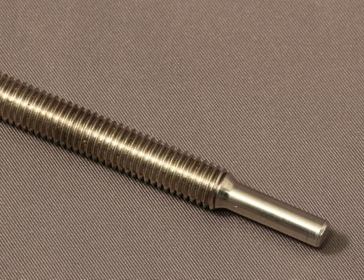
The Z axis has been causing me the most trouble, it doesn't move as smoothly as the other two axes and although it ascends smoothly while doing the layers it tends to be a bit jerky moving faster which seems to be causing one side or the other to loose steps. In an attempt to improve the reliability I've upgraded the shaft couplings to some proper machined aluminium ones from the printed originals, they're from Ebay fairly cheap although it takes a week or so for them to arrive. I've also changed the rods from the original cheap zinc plated steel studding to some stainless steel that has much better cut threads. To mate the new lead screws with the couplings dad suggested turning the end of the threaded rod down so that it is a really tight fit in the shaft coupling rather than using the popular 5mm to 8mm model couplings and just clamping down on the thread. This should ensure there is no slop in the coupling as there is much better surface contact between the shaft and the coupling this way.
Power Supply
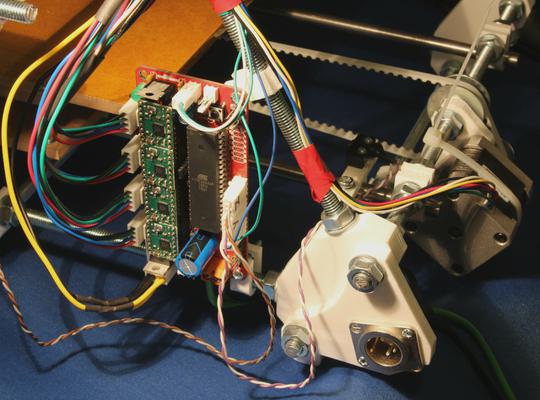
The final upgrade has no effect on the print quality at all but it is a lot easier to use with a decent power supply than it was when I had it hooked up to an old PC power supply that was lying around on the desk. The RepRap has no sensible way of housing a standard ATX powersupply within its frame and there seems no real standard way to hook power up to it. Adrian Bowyer has a part which bolts on to one of the feet of the frame and holds a standard XLR connector, since I bought the kit of parts from him I had one included. This seems a good solution, although I didn't like using a 3 pin XLR for power because of years spent playing with sound kit where it's used for microphones and the cabling can't handle the current used here. I looked at a variety of options and settled on the 4 pin XLR instead. This is a good locking connector and is rated at 10 amp per contact, I'd recommend not hot-plugging it though, connect it and then turn on the PSU especially if the bed is likely to power up immediately you turn it on. Mine is wired up with pins 1 and 3 being 12V and 0V for the main circuit and pins 2 and 4 12V and 0V for my future heated build platform.
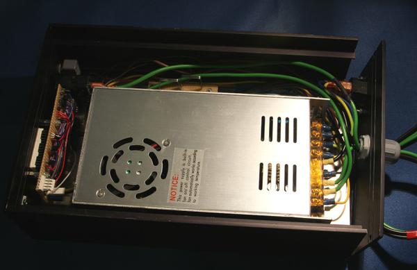
The power supply is recommended on the RepRap wiki, and I got one posted in a reasonable amount of time and it does seem to work very well, especially considering the price. I was very concerned about hooking up a mains lead directly to this thing, even with the printable contact cover. I could see myself tripping over the power lead and ripping the wires out of the screw terminals and having mains voltages flailing around. I decided to build it into a proper metal enclosure with some added features along the way. I added a fused power inlet with a standard IEC connector like a PC power supply. this means if you trip over the lead particularly badly you'll have a safe connector waving around not bare wires. Internally I wired up all the connections to the power supply with crimped blades to avoid stray strands of wire bridging contacts. Mains Earth is connected to the DC 0V rail for safety, this ensures any connection between live or neutral and the DC circuit will blow a fuse or earth breaker. There's a reset-able 10A breaker on the front panel in the circuit for the heated bed which I have yet to build. This is just to make sure if a resistor gets shorted to the aluminium sheet for example that the bed will be disconnected before the power supply melts.
I put a PC fan grill on the top just bolted over a round hole in the aluminium. This more or less lines up with the cooling fan that's built into the power supply. It doesn't run continuously but you'll occasionally here it spin up.
The final, and most complicated part, of the design was the current monitors. It's always useful to know how much power you're using, I did have a multi-meter hooked up in the circuit with the PC power supply, but I wanted a more permanent solution. To measure the current, I used a PIC16F872 and a pair of 0.05Ω 5W power resistors. The nominal maximum current on each channel is 10A so the maximum voltage drop is 0.5V. To improve the resolution of the ADC measurements I used the voltage reference input on the PIC, I was going to use a proper Vref diode, but I couldn't find one with a suitable value (I wanted 2.56V) so I used a 22 turn trim pot and adjusted it to 2.56V with a good multi-meter.
To deal with the current measurement, I multiply the incoming values by 5 done in three operations (b = (a << 1), b = (b <<1), b += a). There's actually a 16 level running average carried out on the incoming values, a sum in 16bit registers of the 10bit ADC values is finally shifted down by 4 (/ 16). This is passed through a binary to BCD conversion routine I wrote which gives a 16 bit packed BCD format value in 10mA units. Displaying this is very straight forward, I assume the largest current to be displayed is 9.99A so simply show the integer Amps value bit wise or-ed with the decimal point and then display the 100mA and 10mA digits. I'd like to add a gain 5 op-amp circuit and a smoothing cap to isolate the power resistors a bit to reduce the noise which affects both the lower 2 digits at the moment.
7 segment display driving is pretty straight forward, a BCD value is passed to a look-up function which generates the 8bit value that will light the appropriate segments. The actual display is interrupt driven, a timer interrupt shifts on to the next of the 6 characters and then displays a value from RAM. The values in RAM are periodically updated by the main loop code.
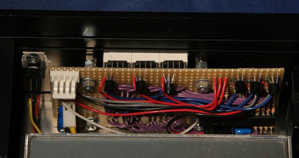
I happened to have some common anode displays around so I used them, I used a simple high side switch based around the 2N3906 to enable one out of the six digits at a time. The only other part of the system is a 7805 regulator which I bolted to the chassis as it will need to supply in excess of 100mA to drive a digit and is regulating down from 12V so is going to dissipate over 700mW so would be a bit warm in free air.
I've uploaded the complete KiCAD project as well as PDF schematic this time. You should be able to open it in KiCAD using the "Import Archive" option in newer releases, otherwise just unzip and open the project. The source code for the power supply meter is in PIC 16F assembly code and was written and debugged in MPLABX on Linux.
| Attachment | Last Update | Size |
|---|---|---|
| KiCad project | Feb. 12, 2017, 12:19 p.m. | 7.0 KB |
| Schematic | Feb. 12, 2017, 12:19 p.m. | 82.8 KB |
| PIC source code | Feb. 12, 2017, 12:19 p.m. | 6.6 KB |
Comments
Posting comments is not currently possible. If you want to discuss this article you can reach me on twitter or via email.
