Memory Tool
Last updated: April 20, 2007, 4:45 p.m.
Introduction In some ways a Z80 processors program storage is easier to get at than modern flash based micro-controllers. However, modern micro-controllers usually have suitable software available for modern computers. I was faced immediately with the problem that the only methods available to me for reading and writing parallel memory chips generally involved lots of binary or hexadecimal number entry and reading and were really very slow. What I wanted was a way to read the contents of the EPROM chip into a text file on my computer, or to write a text file containing the op-codes I wanted run, and then download them into the FRAM chip I had.
Interface Design
PC Port
The first thing to choose was a way of getting data in and out of my laptop. It's not a new laptop, however it is modern enough to be sadly lacking an RS232 serial port, I have no experience making parallel port peripherals, and had no real desire to learn now as this port is also disappearing. However I did have a "USBMOD2" unit from Elexol, (no longer available, although other FTDI parts will do the job now). This unit emulates a serial port as far as the connected PC is concerned, with drivers built into modern Linux kernels, as well as being available for MacOS and Windows, and even the old dusty computers hiding in corners have USB ports these days. The MOD2 is particularly interesting, the computer uses it as a serial port, but the circuit sees an 8-bit bi-directional bus, which made it near perfect for what I wanted. The ideal device would have been one of Elexol's USB I/O 24 devices with three 8 bit parallel I/O registers, since the single 8-bit interface didn't provide any room for control signals as well as data. However, making do is always cheaper and faster when you have to wait for postage.
Address Buffering The address for the 2Mbit EPROM obviously went up to 18 lines, to provide this and data via a single 8-bit bus I used 3 8-bit latches (74HC574 ICs) (the third using only 2 lines.) This however still presented a problem, that I had to write to latches without any lines to use for clocking data into them. The only outputs from the USBMOD2 are an active high wait type signal indicating the device is busy and you shouldn't read from it, and a similar line that goes low when data is available. I toyed with the idea of having a counter that would just clock on one each time a byte was written, select the latches one at a time, and then finally the memory chip, and decided it was going to end up taking too many parts to build on proto-board anyway, instead I opted for an intelligent controller, which proved useful as I expanded the address bus by two bits after building the board, which only required adding a bit of code and half a dozen wires.
Programmer Intelligence I use the term intelligence loosely, the intelligence of the programmer was actually a PICAXE chip since I had these lying around and the BASIC programming language made writing the code very fast. Any old PIC with at least 12 I/O pins should do, there are 8 outputs and 3 inputs. All the PIC is doing in the circuit is controlling the chip select and clock signals for the various other components, it's only interaction with the data bus is that it reads bit0 to decide whether the PC wants a read or write cycle.
To get around the problem of having no spare lines for control, I defined a rigid 5 byte read/write cycle.
- Byte 1: Low memory address byte
- Byte 2: Middle memory address byte
- Byte 3: High memory address byte (allows 18-bit addressing to access the 2Mb ROM)
- Byte 4: Read/Write byte, actually only bit 0 needs to be set (read=0x01, write=0x00)
- Byte 5: Data byte, is a read or write depending on what the last byte said
Since the address bus on the programmer board is not shared by anything I wired the \CS signal on the latches to ground, meaning they are always providing output. RB0 and RB1 on my PIC were connected to \RD and WR on the USB module, respectively, the \RD line fetches a byte on a low to high transition, and drives the bus while low, WR adds the byte from the bus to the module's internal FIFO when driven low. RB2 drives the \OE or read line of the memory chip, RB3 controls the \CE chip enable/select line on the memory chip and RB4 is connected by a switch to the \WE write enable line. This line is switched because unlike the other control lines, this one is obviously not present on the ROM, in fact on the larger memory ROM chip (the FRAM was only 8kB) this was address 14. Similarly power for the 28 pi FRAM was switched, on the ROM chip this pin was used for A17. Lastly, the outputs RB5-7 were used to drive the three latches, low byte to high byte. On the inputs, RC0 was connected to \RXF (data ready) signal from the USB module, RC1 to \TXE (clear to send) and RC2 to D0 on the bus to get the read/write instruction.
The program flow therefore goes something like,
- Wait for \RXF (RC0) to go low.
- Bring \RD (RB0) low
- Pulse the low byte clock (RB5)
- Push \RD high again
- Wait for \RXF to drop again
- Bring \RD low again,
- Pulse middle byte low (RB6)
- Bring \RD high again
- Wait for \RXF
- Bring \RD low
- Pulse high byte low (RB7)
- Bring \RD high
- Wait for \RXF
- Bring \RD low
- Read bit 0 (RC2)
- Take \RD high again
If RC2 was high, do a read cycle, that's read from ROM to PC,
- Take \CE low, this also latches the address into the memory chip with the FRAM module.
- Take \OE low, this makes the memory drive the bus
- Wait for \TXE should be clear since there shouldn't be anything in the buffer
- Pulse WR low on the USB module to send a byte to the PC
- Bring \OE back up
- Bring \CE back up,
- Loop.
If RC2 was low, do a write cycle, that's write a byte from the PC to the chip (clearly only works with a RAM or FLASH type chip),
- \RXF
- Take \RD low
- Take \CE low to latch address
- Pulse \WE low to write data
- Take \CE high
- Take \RD high again
- Loop.
Microprocessor Code I have re-written the code for the PIC in this project in MPASM (Microchip Assembler). This makes the operation some what faster as the old BASIC code I had written was slow even for BASIC code. The listing and the HEX file for the PIC16F872 that I used are available for download as a zip file (See bottom of page). For more info on the code see the article.
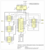
Circuit Diagram I hear you, trying to piece together what I've done from that jumbled nonsense is not much fun, and a picture as they say is worth a thousand words and all. A new and improved circuit diagram is now available, hopefully less incomprehensible than the previous effort the file is available as png to view online or as a PDF (see attachments at the bottom of the page).
PC Software Right, well the hardware is now fairly well documented, and the software would be fairly simple, and indeed it is, I hope to add some functionality to it in the future, but the current version is available here.
The code is written in Python, and uses the PySerial extension which you will need to obtain and install first. Obviously if you're doing it the same way I did you'll also need the FTDI driver for the USBMOD2 unit for your platform. As far as I'm aware the Python code should be okay on any platform, although you will need to change the serial port definition. I found the module clocked up the addresses on my Linux box if I unplugged it and plugged it in again without rebooting the PC, so you'll have to increase the number each time (i.e. /dev/ttyUSB0, /dev/ttyUSB1 etc.) on Windows of course you would need to use the name COM1, COM2 etc. Alternatively you can just give a number where that describes the port number on your machine, i.e. on my old desktop with one serial port on board the USB module appears as COM2 so can be addressed as 1 (the on board port is COM1 addressed as 0).
The actual reading and writing is handled by a "memchip" class with methods read() and write() to make life easier, this class is declared in full in both the memread.py and memwrite.py files. The memread.py script outputs a file with a form "AAAAA DD" where A is a single Hexadecimal address digit and D is a single Hex data byte, you can set how many lines to read in the file. Similarly memwrite.py accepts an input file in the same format, running the script prompts you for a file name. You can skip lines when writing code to be sent to the memory chip just by changing the address at the start of the line, you could even write programs backward if you want since the data byte is sent to the address at the start of the line regardless of where the last byte went. The gap between address and data can be a single space or tab, and no blank lines are allowed at the moment. anything after the two digit Hex number for data is ignored so you can comment as much as you like here. I hope to add ignoring blank lines, comment lines, and a simpler line numbering system sometime. The actual files are attached at the end of the article.
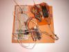
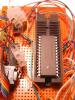
Updates 20 Apr 07 Original article written 07 Aug 07 Update 1: added the link to MPASM source code for the PIC 08 Aug 07 Update 2: added improved circuit diagram 08 Aug 07 Update 3: added some pretty pictures of my prototype version.
| Attachment | Last Update | Size |
|---|---|---|
| Circuit Diagram (PDF) | April 23, 2014, 9:06 p.m. | 1.2 MB |
| PIC ASM and HEX (zip) | April 23, 2014, 9:06 p.m. | 14.1 KB |
| memread.py | April 23, 2014, 9:06 p.m. | 1.1 KB |
| memwrite.py | April 23, 2014, 9:06 p.m. | 1.1 KB |
Comments
Posting comments is not currently possible. If you want to discuss this article you can reach me on twitter or via email.